o ring design guide
O-Ring Design Guide: A Comprehensive Overview (Updated 04/15/2026)
This guide details crucial aspects of O-ring selection‚ focusing on dimensions like ID and cross-section‚ alongside standards such as AS568 and ISO 3601.
O-rings are deceptively simple yet remarkably versatile sealing solutions‚ employed across a vast spectrum of industries – from aerospace and automotive to hydraulics and plumbing. Effective O-ring design isn’t merely about selecting a rubber ring; it’s a holistic process demanding careful consideration of the application’s operating parameters‚ fluid compatibility‚ and material properties.
Proper design ensures reliable performance‚ preventing leaks and maintaining system integrity. Key to this is accurately determining the necessary dimensions – inside diameter (ID)‚ outside diameter (OD)‚ and cross-section (C/S) – and aligning them with established standards like AS568‚ ISO 3601‚ JIS‚ and BS. Understanding these standards is paramount for interchangeability and sourcing. Selecting the correct elastomer‚ considering chemical compatibility‚ is equally vital for longevity and preventing premature failure.
Understanding O-Ring Dimensions
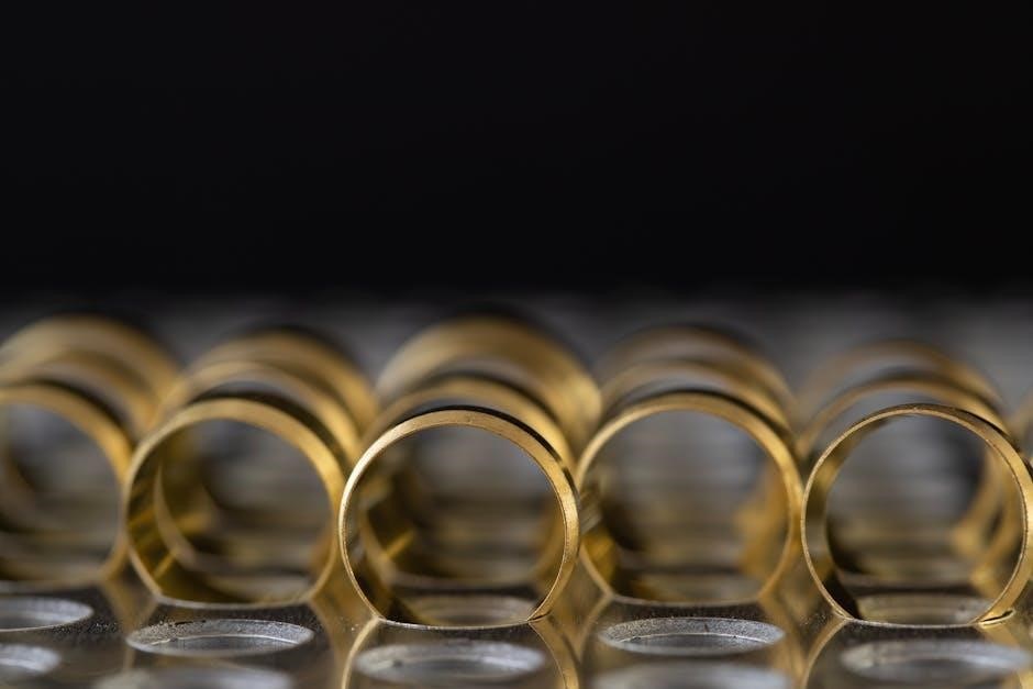
Accurate dimensional analysis is fundamental to successful O-ring application. Three primary dimensions define an O-ring: Inside Diameter (ID)‚ Outside Diameter (OD)‚ and Cross-Section (C/S) or width. Measuring these correctly‚ whether on an existing O-ring or the gland it will inhabit‚ is crucial. The ID dictates the fit within the groove‚ while the C/S determines the sealing force.
Determining the ID is often the starting point‚ frequently referenced using AS568 dash numbers. The OD is less critical but impacts compression and potential for extrusion. The C/S must be appropriately sized for the pressure and gap to be sealed. Precise measurement‚ using calipers‚ is essential for optimal performance and avoiding premature failure due to improper fit.
Inside Diameter (ID) and its Importance
The Inside Diameter (ID) is the most critical dimension for O-ring selection‚ defining its fit within the gland or mating components. It’s typically specified using the AS568 dash number system‚ a standardized industry convention. Accurate ID determination ensures proper compression during installation‚ creating a reliable seal.
Selecting the correct ID prevents issues like roll-over (too small) or excessive compression (too large). Measuring the gland’s internal diameter is paramount if an existing O-ring isn’t available for reference. Proper ID selection directly impacts sealing effectiveness and longevity‚ minimizing leakage and downtime. Prioritize precision when measuring to guarantee optimal performance.
Outside Diameter (OD) Considerations

While the Inside Diameter (ID) is primary‚ the Outside Diameter (OD) is crucial for proper fit within the gland’s housing. It dictates the O-ring’s ability to be retained and prevents extrusion – a common failure mode where the O-ring is forced into a clearance gap.
OD selection must account for gland design and available space. Ensuring sufficient radial compression without overstressing the O-ring is key. The OD influences the overall sealing system’s geometry and compatibility with surrounding components. Careful consideration of OD‚ alongside ID and cross-section‚ guarantees a robust and reliable seal‚ maximizing operational lifespan and minimizing potential failures.
Cross-Section (C/S) or Width Selection
The cross-section‚ or width‚ of an O-ring significantly impacts its sealing performance and longevity. It determines the amount of compression achieved during installation‚ directly influencing the seal’s ability to prevent leakage. A correctly sized cross-section ensures adequate contact with both mating surfaces‚ creating a reliable barrier.
Selecting the appropriate C/S involves balancing compression requirements with potential for over-compression. Insufficient compression leads to leakage‚ while excessive compression can cause premature wear and failure. The width also correlates with the gland’s depth‚ demanding precise dimensional coordination for optimal sealing. Proper C/S selection is vital for a durable and effective O-ring application.
Standard O-Ring Sizes and Standards
O-rings adhere to various international standards to ensure interchangeability and consistent performance. The AS568 standard is the most widely recognized in North America‚ providing a comprehensive dash number system for identifying sizes. Metric O-rings follow ISO 3601‚ offering a parallel sizing convention used globally.
Additionally‚ Japanese Industrial Standards (JIS) and British Standards (BS) define specific O-ring dimensions for regional applications. Understanding these standards is crucial for sourcing the correct O-ring for a given application and ensuring compatibility with existing hardware. Utilizing standardized charts simplifies selection and guarantees a proper fit.
AS568 O-Ring Size Chart – The Industry Standard
The AS568 standard is the cornerstone of O-ring sizing in many industries‚ utilizing a dash number system to denote Inside Diameter (ID) and Cross-Section (C/S). This chart provides a quick reference for selecting the appropriate O-ring based on these two critical dimensions. Determining the ID and C/S of either the existing O-ring or the gland is the initial step.
Once these measurements are known‚ referencing the AS568 chart allows for precise identification of the corresponding dash number. This ensures compatibility and proper sealing performance. The AS568 standard simplifies the process of specifying and procuring O-rings‚ promoting consistency across applications.
Metric O-Ring Sizes (ISO 3601)
ISO 3601 defines the standard for metric O-ring dimensions‚ offering an alternative to the AS568 system‚ particularly prevalent in European and international applications. This standard specifies O-rings based on their inner diameter (ID) and cross-section (C/S)‚ expressed in millimeters. Utilizing metric O-rings requires careful attention to these dimensions for a proper fit.
Unlike the dash number system of AS568‚ ISO 3601 directly uses the measured values. Selecting the correct metric O-ring involves accurately determining the ID and C/S of the gland or existing seal. Marco Sealing Solutions provides comprehensive indexes of these sizes‚ facilitating accurate selection and ensuring optimal sealing performance in metric systems.
JIS O-Ring Standards (Japanese Industrial Standards)
Japanese Industrial Standards (JIS) offer another set of specifications for O-ring dimensions‚ commonly used in Japanese manufacturing and applications requiring adherence to these standards. Like ISO 3601 and AS568‚ JIS standards define O-rings based on their inner diameter (ID) and cross-sectional diameter (C/S). Understanding these specifications is crucial when working with Japanese-made equipment or components.
JIS standards provide a distinct sizing system‚ necessitating careful conversion or direct sourcing of JIS-compliant O-rings. Marco Sealing Solutions‚ among others‚ provides indexes detailing these dimensions‚ ensuring compatibility and proper sealing within JIS-specified systems. Accurate measurement and selection are paramount for reliable performance.

BS O-Ring Standards (British Standards)
British Standards (BS) represent yet another crucial set of specifications for O-ring dimensions‚ frequently encountered in applications originating from the United Kingdom and adhering to British engineering practices. Similar to AS568‚ ISO 3601‚ and JIS standards‚ BS standards categorize O-rings based on their inner diameter (ID) and cross-sectional diameter (C/S)‚ ensuring interchangeability within systems designed to these specifications.
When integrating O-rings into British-engineered systems‚ referencing the appropriate BS standard is essential for achieving a reliable seal. Marco Sealing Solutions provides comprehensive indexes of these dimensions‚ facilitating accurate selection and compatibility. Proper identification and sourcing of BS-compliant O-rings are vital for optimal performance and longevity.
Materials and Compound Selection

Selecting the correct O-ring material is paramount for ensuring long-term reliability and performance. This decision hinges on understanding elastomer properties and their compatibility with the intended application’s operating conditions and media. Factors like temperature range‚ pressure‚ and chemical exposure significantly influence material choice.
Common materials include NBR (Buna-N) for oil resistance‚ EPDM for water and weathering‚ Viton (FKM) for high temperatures and harsh chemicals‚ and Silicone for extreme temperatures; A thorough chemical compatibility assessment‚ utilizing compatibility charts‚ is crucial to prevent swelling‚ degradation‚ or failure. Careful material selection directly impacts sealing effectiveness and system lifespan.
Elastomer Properties and Compatibility
Elastomers exhibit unique properties like elasticity‚ resilience‚ and resistance to various fluids. Understanding these characteristics is vital for optimal O-ring performance. Key properties include tensile strength‚ elongation‚ hardness‚ and compression set – all influencing sealing capability and longevity.
Compatibility refers to the elastomer’s resistance to degradation when exposed to specific chemicals. Swelling‚ shrinking‚ or hardening can compromise the seal. Thoroughly evaluating chemical resistance charts is essential‚ considering both short-term and long-term exposure. Temperature also impacts compatibility; a material suitable at room temperature may fail at elevated temperatures. Proper elastomer selection prevents premature failure and ensures reliable sealing.
Common O-Ring Materials: NBR‚ EPDM‚ Viton‚ Silicone
Several elastomers are frequently used for O-rings‚ each offering distinct advantages. NBR (Nitrile Butadiene Rubber) excels in oil resistance‚ making it ideal for fuel systems and hydraulics. EPDM (Ethylene Propylene Diene Monomer) provides excellent resistance to water‚ steam‚ and weathering‚ suitable for outdoor applications.
Viton (Fluoroelastomer) boasts superior resistance to high temperatures‚ chemicals‚ and fuels‚ often used in harsh environments. Silicone offers exceptional temperature resistance and flexibility‚ commonly found in food and medical applications. Choosing the right material depends on the specific application’s temperature‚ pressure‚ and fluid compatibility requirements‚ balancing performance and cost.
Chemical Compatibility Considerations
Selecting an O-ring material requires careful evaluation of chemical exposure. Incompatible fluids can cause swelling‚ shrinking‚ or degradation of the elastomer‚ leading to premature failure. NBR is vulnerable to ketones and strong acids‚ while Viton offers broad chemical resistance but can be affected by certain amines.
EPDM is generally good with polar substances but poor with petroleum oils. Silicone exhibits good resistance to many chemicals but has limited compatibility with hydrocarbons. Consulting a chemical compatibility chart is crucial; these charts detail elastomer performance with various substances‚ ensuring optimal sealing and longevity in specific operating conditions. Proper material selection prevents leaks and system downtime.
O-Ring Gland Design
Effective O-ring sealing hinges on proper gland design. Gland dimensions must accommodate O-ring compression and prevent extrusion. Width and depth are critical; insufficient width leads to extrusion‚ while excessive compression damages the O-ring. Surface finish significantly impacts sealing – a smooth finish minimizes friction and wear.
Tolerance analysis is essential‚ accounting for variations in O-ring size and gland machining. Proper gland design ensures consistent sealing performance. Careful consideration of these factors maximizes O-ring life and prevents costly failures. A well-designed gland provides a reliable and long-lasting seal‚ crucial for system integrity.
Gland Dimensions for Optimal Sealing
Achieving optimal sealing requires precise gland dimensioning. Width should allow for sufficient compression – typically 20-30% of the O-ring cross-section – without overstressing the elastomer. Depth must accommodate the O-ring’s cross-section‚ providing adequate support and preventing roll-over.
Radial clearances are also vital; too much clearance risks extrusion‚ while too little increases friction and wear. Careful calculation‚ considering material properties and operating conditions‚ is essential. These dimensions directly influence sealing force and longevity. Proper gland dimensions ensure reliable performance and prevent premature failure‚ maximizing system uptime and safety.
Surface Finish Requirements for O-Ring Glands
Gland surface finish significantly impacts O-ring sealing performance and lifespan. A smooth surface minimizes friction during installation and operation‚ reducing wear and heat buildup. However‚ excessively smooth surfaces can lead to stick-slip behavior.
Generally‚ a surface roughness of 16 to 32 micro-inches Ra is recommended. This provides sufficient texture for lubrication retention while minimizing abrasion. Avoid sharp edges or burrs‚ which can damage the O-ring during installation or operation. Proper surface treatment‚ like honing or lapping‚ ensures optimal sealing and prevents premature failure‚ contributing to long-term reliability.
Tolerance Analysis in Gland Design
Accurate tolerance analysis is vital for reliable O-ring sealing. Variations in gland dimensions – ID and OD – directly affect compression and squeeze‚ impacting sealing force.
Consider manufacturing tolerances for both the O-ring and the gland. A worst-case analysis determines the minimum and maximum compression‚ ensuring adequate sealing even with dimensional deviations. Too little compression leads to leakage‚ while excessive compression causes increased friction and potential damage. Statistical analysis‚ like Monte Carlo simulation‚ can refine tolerance stacks and optimize gland design for consistent performance and longevity.
O-Ring Installation Best Practices

Proper installation is paramount for maximizing O-ring lifespan and performance. Avoid sharp tools that can nick or cut the elastomer during placement‚ compromising the seal. Carefully inspect the gland for burrs or sharp edges before installation‚ removing any imperfections that could damage the O-ring.
Lubrication significantly eases installation and extends service life. Use a compatible lubricant to reduce friction and prevent twisting or rolling during placement. Avoid excessive stretching or compression‚ as this can pre-damage the O-ring. Ensure the O-ring seats correctly within the gland‚ avoiding pinches or uneven distribution.
Preventing Damage During Installation
O-rings are susceptible to damage if not handled carefully during installation. Sharp tools‚ like screwdrivers or picks‚ must be avoided as they can easily cut or nick the elastomer‚ leading to premature failure. Thoroughly inspect the O-ring gland for any burrs‚ sharp edges‚ or surface imperfections before attempting installation.
Remove any detected flaws to prevent damage; Avoid forcing the O-ring into the gland; excessive force can cause stretching‚ tearing‚ or rolling. Proper gland design and surface finish are crucial preventative measures. Gentle‚ controlled placement is key to maintaining the O-ring’s integrity and ensuring a reliable seal.
Lubrication for Easy Installation and Extended Life
Proper lubrication significantly eases O-ring installation and dramatically extends its service life. A compatible lubricant reduces friction during installation‚ preventing rolling‚ twisting‚ or pinching of the seal. This minimizes stress on the elastomer‚ reducing the risk of damage. Select a lubricant specifically designed for O-ring applications‚ considering material compatibility.

Avoid petroleum-based lubricants with certain elastomers‚ like EPDM‚ as they can cause swelling and degradation. Lubrication also provides a dynamic seal‚ filling minor imperfections and enhancing sealing performance. Regular relubrication‚ based on application demands‚ can further prolong O-ring life and maintain optimal functionality.
Stretch and Compression Considerations
O-ring stretch during installation is inevitable‚ but excessive stretch can lead to permanent deformation and reduced sealing capability. Aim for a controlled stretch‚ typically within 3-5% of the original ID. Conversely‚ excessive compression can cause extrusion‚ particularly in high-pressure systems. Proper gland design is crucial to manage compression.
Consider the O-ring’s durometer (hardness) when evaluating stretch and compression. Softer materials stretch more easily‚ while harder materials require greater force. Maintaining appropriate stretch and compression levels ensures optimal sealing performance and maximizes O-ring lifespan‚ preventing premature failure due to material fatigue or extrusion.
O-Ring Failure Modes and Troubleshooting
Understanding O-ring failure modes is vital for effective troubleshooting and preventing recurrence. Common failures include extrusion – material forced into gland clearances under high pressure – and compression set‚ where permanent deformation reduces sealing ability. Other modes encompass abrasion from surface imperfections‚ chemical attack degrading the elastomer‚ and improper installation causing damage.
Identifying the failure mode guides corrective action. Extrusion necessitates gland redesign or pressure reduction. Compression set demands material change or improved gland design. Chemical attack requires a compatible elastomer. Careful inspection‚ coupled with knowledge of operating conditions‚ allows for accurate diagnosis and implementation of preventative measures‚ ensuring long-term reliability.
Causes of O-Ring Failure (Extrusion‚ Compression Set‚ etc.)
Several factors contribute to O-ring failure‚ impacting sealing performance and system integrity. Extrusion occurs when the O-ring is forced into excessive clearances between mating components under high pressure‚ leading to rupture. Compression set‚ a permanent deformation‚ results from prolonged exposure to high temperatures or incompatible fluids‚ diminishing sealing force.
Additional causes include abrasion from rough surfaces‚ swelling or degradation due to chemical incompatibility‚ and improper installation causing nicks or twists. Environmental factors like temperature extremes and UV exposure also accelerate deterioration. Addressing these root causes through proper material selection‚ gland design‚ and installation practices is crucial for maximizing O-ring lifespan.
Identifying Failure Modes for Corrective Action
Accurate identification of O-ring failure modes is paramount for implementing effective corrective actions. Visual inspection can reveal signs of extrusion (stretched or broken rings)‚ compression set (permanent deformation)‚ or abrasion (surface damage). Analyzing the fluid compatibility and operating conditions helps pinpoint chemical attack or swelling.
Detailed examination of the gland and mating surfaces can expose issues like sharp edges or improper clearances. Documenting the failure – including photographs and operational data – aids in root cause analysis. Based on the identified mode‚ solutions range from material upgrades and gland redesign to improved installation procedures and lubrication‚ ensuring long-term sealing reliability.